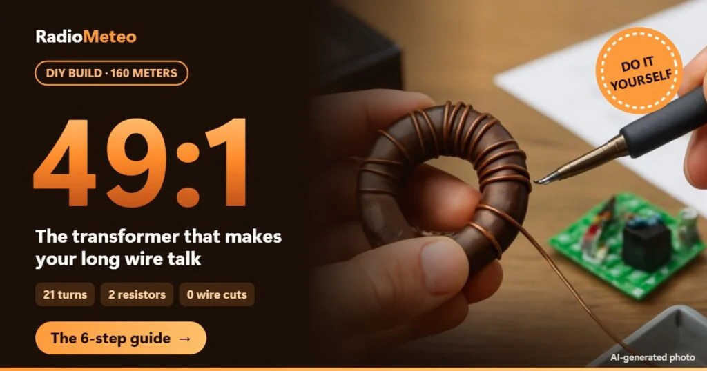
Got a long wire An antenna made from a long piece of wire. in the garden and want to use it on 160 meters? A home-made 49:1 transformer does the job, and it costs less than a pizza. Here is how I would build one for a long wire (an antenna made of one single long wire) of about 155 m, fed at one end.
How to build a 49:1 transformer for a 155 m long wire on 160 meters: parts, 21 turns with a tap at turn 3, a two-resistor test and tuning by folding the wire.
 Radiotransmits at 50 ohms
 Tunerfine-tunes the match
 Coax cablewith a choke near home
 49:1 transformerlowers impedance 49 times
 155 m wireradiates on 160 meters
Why a 49:1 transformer on a 160 m wire
On 160 meters, a wire of about 155 m is one full wavelength long. The wavelength is the distance the signal travels during one oscillation: at 1830 kHz Kilohertz, thousands of vibrations per second. it is about 164 m. The real wire is a bit shorter, because in copper the signal travels slightly slower than in air.
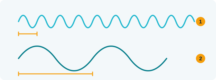
- High frequency: short, tight waves (and shorter antennas)
- Low frequency: long, wide waves (and longer antennas)
Teaching illustration created by RadioMeteo.
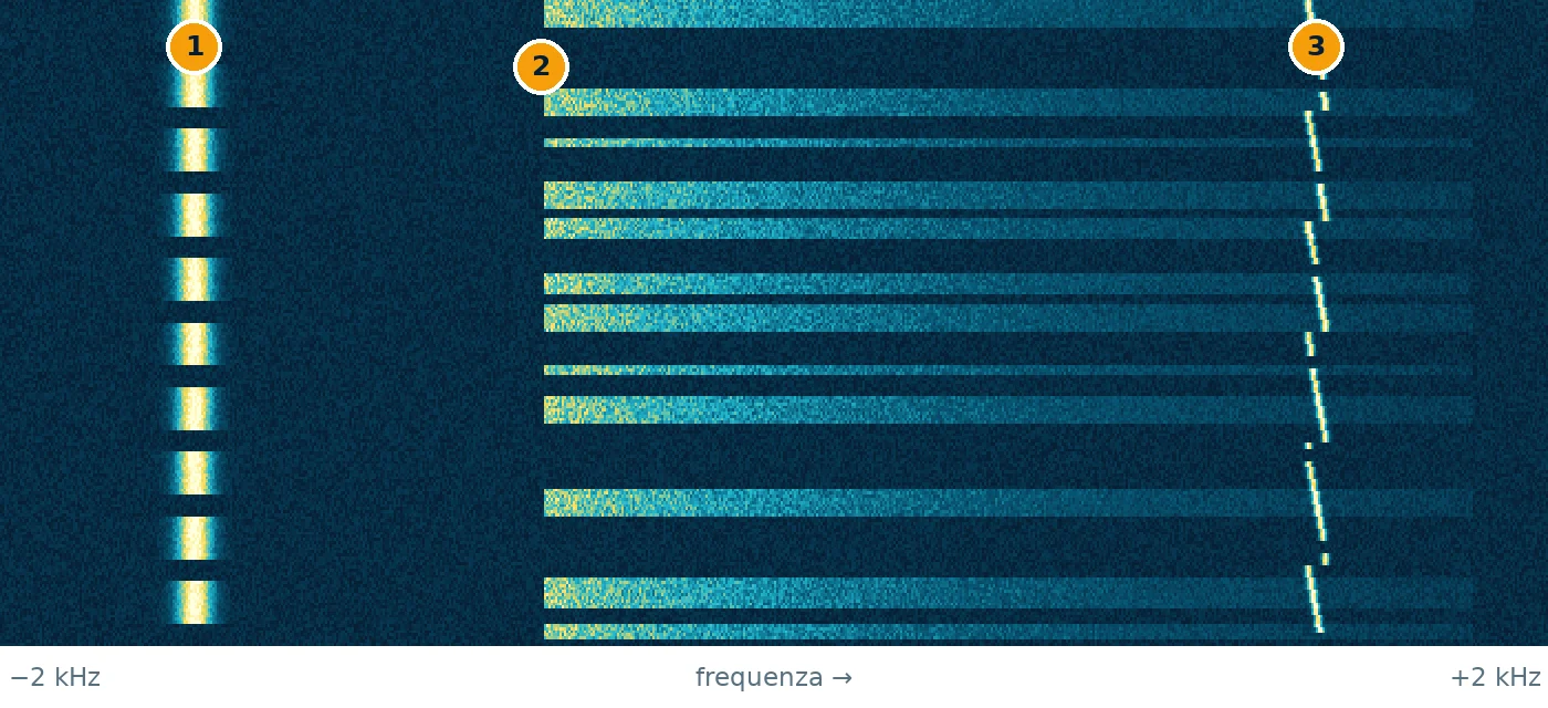
time ↓ · frequency →
- CW: a thin line that switches on and off: it is Morse code
- SSB voice: a band that lights up in bursts, following the syllables
- FT8: a tiny trace that hops between tones every 15 seconds
Teaching illustration created by RadioMeteo, not a real recording.
At the end of a wire like this the impedance A measure of how well the antenna, cable and radio pass the signal to each other. is very high. Impedance is the “resistance” the antenna offers to radio frequency The “channel” a station transmits on.: here it is around 2500–3500 ohms. The radio works at 50 ohms, and my Daiwa CNW-419 tuner A box that “matches” the antenna to the radio when they don’t quite get along. only matches from 10 to 250 ohms.
The transformer works like an adapter: it divides the impedance by 49. 2500 ÷ 49 is about 51 ohms, a value the radio handles with no effort. Without it, the energy bounces back and the SWR A number that tells you whether the antenna and radio “get along”: the closer to 1, the better. (standing wave ratio, how much energy comes back to the radio) goes sky high. The 49:1 transformer does not tune the antenna: it brings it close to 50 ohms, and then the tuner only makes small corrections.
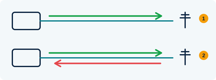
- Well-tuned antenna: almost all the energy goes out into the air
- Badly tuned antenna: part of the energy bounces back to the radio (high SWR)
An SWR meter measures how much comes back: the closer to 1:1, the better.
Teaching illustration created by RadioMeteo.
What you need to build it
The list is short. The table shows the parts that really matter, with quantities:
| Part | Quantity |
|---|---|
| FT240-43 ferrite toroid (a 61 mm ferrite ring) | 2, better 3 |
| 1.5 mm enamelled copper wire | 3 m |
| IP65 weatherproof box, SO-239 connector and 2 M6 stainless bolts | 1 set |
| Carbon film resistors, 2.2 kΩ and 270 Ω, for testing | 1 + 1 |
You also need a soldering iron of at least 60 W, a multimeter and an antenna analyzer, for example a NanoVNA (a small instrument that measures SWR A number that tells you whether the antenna and radio “get along”: the closer to 1, the better. at every frequency The “channel” a station transmits on.). On the coax The round cable, like a TV cable, that carries the signal from the antenna to the radio. I would also add a 1:1 choke A “plug” made of coiled cable or ferrite that stops interference on the outside of the coax.: an FT240-31 toroid with 12 turns of RG58, which stops radio frequency on the cable shield.
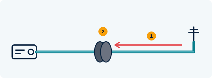
- Common-mode current: noise travels back to the radio on the outside of the shield
- The choke (ferrite or coiled cable) blocks it, the real signal passes
A ferrite only helps if the noise really travels on the cable.
Teaching illustration created by RadioMeteo.
Build the 49:1 transformer in 6 steps
The transformer is one single wire wound on the toroids, with a tap, meaning a connection point part of the way along.

- The core. Stack the toroids and wrap them with PTFE tape: it holds the stack together and protects the wire enamel from sharp edges.
- The first turns. Leave a 10 cm tail, point A, and wind 3 tight turns. A turn is one pass of the wire through the hole of the ring.
- The tap. After the third turn, twist the wire on itself twice: you get a 3 cm loop, point B.
- The other turns. Keep winding in the same direction until you reach 21 turns in total. Leave a 1 cm gap between start and end and a final tail, point C.
- The connections. A goes to the SO-239 ground and to the counterpoise bolt (an 8–10 m wire laid on the ground), B to the centre pin, C to the antenna bolt.
- The test. Put the two resistors in series (2470 ohms, almost 49 × 50) between the two bolts and sweep from 1.7 to 2.0 MHz Megahertz, millions of vibrations per second: the unit used to measure frequency.: SWR A number that tells you whether the antenna and radio “get along”: the closer to 1, the better. must stay below 1.5.
Why 3 and 21? The turns ratio is 21 ÷ 3 = 7, and impedance A measure of how well the antenna, cable and radio pass the signal to each other. changes with the square: 7 × 7 = 49. Many guides use 2 and 14 turns, same ratio: I stick with 3 and 21, because more turns give more inductance, and on 160 meters you need it.
Counting turns sounds easy, but it is where most mistakes happen. I count them out loud: the ferrite A ring of special material that blocks interference on cables. doesn’t mind.
📌 Real case: on a radio forum, a user tested his end-fed A wire antenna fed from one end. matching transformer with resistors from 1.5 to 4.7 kΩ and an analyzer. On 160 m, with 2.2 kΩ and a short jumper, SWR was about 1.7; with a cable of about 5.5 m it rose to 2.1. The lesson: test with a short jumper, or you are also measuring the cable (source).
Tuning: fold the wire instead of cutting it
Start with the wire a bit longer, for example 160 m, and look for the frequency The “channel” a station transmits on. where SWR A number that tells you whether the antenna and radio “get along”: the closer to 1, the better. drops the most. I aim for 1830 kHz Kilohertz, thousands of vibrations per second., so the tuner A box that “matches” the antenna to the radio when they don’t quite get along. has little work to do both above and below. The rule to remember: every metre of wire removed raises the frequency by about 12 kHz.
With 160 m the lowest point usually falls around 1780 kHz. That is 50 kHz short, so there are about 4 m too many. Don’t cut yet: fold the last piece of wire back on itself and twist it, so if you get it wrong you just straighten it.

The first time, fold only two thirds of the calculated length, then half a metre at a time, until the dip lands between 1825 and 1835 kHz. Only then cut: the wire ends up around 155–156 m. When it rains the frequency drops by a few kHz, and that is normal.
💡 Practical tip: tune with the analyzer connected straight to the SO-239 on the box, without radio or tuner: that way you measure the antenna and nothing else.
First connection, safely
Connect radio, tuner A box that “matches” the antenna to the radio when they don’t quite get along. and the coax The round cable, like a TV cable, that carries the signal from the antenna to the radio. to the box. Switch off the radio’s internal tuner and start at 10 W. Once you find the lowest SWR A number that tells you whether the antenna and radio “get along”: the closer to 1, the better., try 100 W for one minute and touch the toroid with the radio off: if it is hot, add a third toroid or use less power on FT8 A digital mode: the computer sends and receives short messages even with very weak signals. (a digital mode that transmits for long stretches without pauses).
No jokes here: at 100 W there are hundreds of volts on the antenna bolt. Never touch the wire while transmitting, and keep it away from power lines, even in case a support gives way.
If your mouse goes crazy when you transmit, read our article on HF noise in an apartment. For more ideas to build, see the page on homemade antennas.
Summary: the 49:1 transformer in a few words
Two or three toroids, 21 turns with a tap at the third, a weatherproof box and two resistors for testing: that turns a 155 m wire into a real 160 meter antenna. You tune it by folding the wire, and the tuner A box that “matches” the antenna to the radio when they don’t quite get along. does the rest, on 80, 40 and 20 meters too.
Have you tried a long wire An antenna made from a long piece of wire. on 160 meters? Which 49:1 transformer did you use?
Further reading
RadioMeteo newsletter
News from RadioMeteo and the CLV programs by e-mail. You can unsubscribe at any time.
Protected by reCAPTCHA: Google Privacy Policy and Terms apply.